
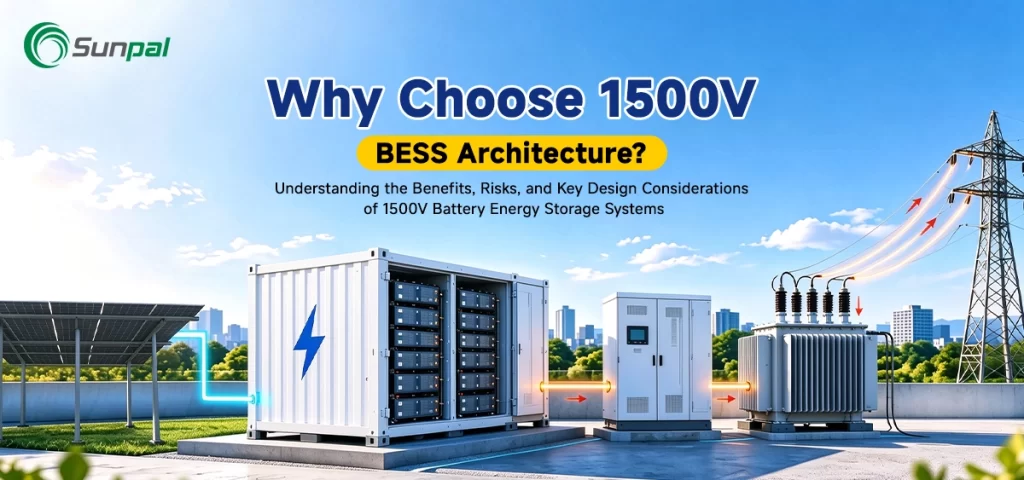
The global energy transition is accelerating, and utility-scale solar projects paired with battery storage are no longer optional—they are essential. As solar farms grow larger and grid operators demand greater flexibility, the architecture of the battery energy storage system (BESS) itself has become a decisive factor in project economics and long-term performance. One of the most significant shifts in recent years is the widespread adoption of 1500V DC architecture.
Once considered advanced, 1500V systems are now the mainstream choice for new utility-scale and large commercial-and-industrial (C&I) deployments. They deliver measurable gains in efficiency and cost, yet they also introduce new engineering demands. Understanding both sides of the equation is critical for developers, EPCs, and asset owners evaluating solar-plus-storage projects. This article provides an in-depth look at the advantages, risks, and practical design considerations for 1500V battery energy storage system architectures.
Why Voltage Architecture Matters in Modern Solar-Plus-Storage Projects
Power equals voltage times current. Raise the DC voltage and the same power can be delivered at lower current. That simple relationship cascades through the entire system: thinner cables, lower resistive losses, fewer parallel strings, and reduced balance-of-system (BOS) costs.
The solar industry learned this lesson first. The transition from 1000V to 1500V photovoltaic systems delivered clear BOS savings and higher system efficiency. Battery energy storage has followed the same path. Today, nearly all major containerized utility BESS platforms ship as 1500V systems by default.
DC Current Comparison for a 1 MW System
How DC bus voltage affects current requirements at the same power output
Example: 1,000,000 W ÷ 1,500 V ≈ 666.67 A
Technical Note: Values represent ideal continuous DC bus current at 1 MW. Actual operating current may vary with state of charge, battery string voltage, temperature, and PCS operating range. Relative current ratios remain consistent when comparing equal power at the stated nominal voltages.
Anatomy of a 1500V BESS Architecture
In a 1500V system, lithium iron phosphate (LiFePO4 or LFP) cells—typically operating around 3.2 V nominal—are connected in long series strings. A single string may contain 360 to more than 400 cells, producing a nominal voltage in the 1150–1330 V range and a maximum near the 1500 V ceiling when fully charged.
These strings feed a high-voltage DC bus that connects directly to a 1500V-rated power conversion system (PCS). The result is higher power density, fewer parallel branches, and a cleaner electrical layout. The architecture works especially well in DC-coupled solar-plus-storage configurations, where the battery and photovoltaic arrays share a common high-voltage DC bus.
Compared with earlier 1000V designs, 1500V systems require fewer combiner boxes, reduced copper, and often fewer PCS units for the same power rating. These advantages, however, only materialize when every component—from insulation to protection devices—is properly specified.
Simplified Single-Line Diagram of a 1500 V DC-Coupled Solar-Plus-Storage System
PV generation and battery storage share a common 1500 V DC link, with bidirectional power conversion to the AC grid or load.
Engineering Note: This is a simplified conceptual single-line diagram, not a construction-ready electrical drawing. Actual system configurations, protection coordination, grounding, isolation, transformer requirements, and voltage ratings must be verified against the selected equipment specifications and applicable electrical standards. The 360–416 cell count is indicative of the specified 1500 V-class battery string configuration and must be confirmed against actual cell voltage and string design.
The Compelling Benefits of Going 1500V
Lower Current, Higher Efficiency
Reducing current by roughly one-third (from 1000V to 1500V at constant power) cuts I²R losses dramatically. Cable losses scale with the square of current, so the same conductor dissipates significantly less heat. Round-trip efficiency improves, and the thermal burden on the system decreases. Over thousands of cycles, even a 0.5–1% gain in efficiency compounds into meaningful energy and revenue advantages.
Meaningful Balance-of-System Cost Savings
Industry analyses consistently show 20–50% reductions in DC-side hardware costs when moving from 1000V to 1500V. Smaller cable cross-sections, fewer parallel runs, reduced connector and fuse counts, and smaller switchgear all contribute. For a multi-megawatt project, these savings can reach hundreds of thousands of dollars in copper and installation labor alone.
Higher Power Density and Simpler Layouts
Longer series strings mean fewer parallel paths. The system becomes more compact, container footprints shrink, and the number of PCS units required for a given power rating often decreases. This is particularly valuable for land-constrained solar farms and urban C&I sites.
Seamless Integration with Modern Solar and PCS Technology
Most new utility-scale solar inverters and hybrid PCS platforms are designed around the 1500V class. Pairing a 1500V BESS with 1500V PV modules creates natural compatibility for DC-coupled architectures, simplifying control and improving overall plant efficiency. Silicon-carbide (SiC) devices further enhance performance at these voltage levels.
Stronger Project Economics
Lower BOS costs, higher efficiency, and improved power density all contribute to a more competitive levelized cost of storage (LCOS). For developers bidding solar-plus-storage projects, these advantages can improve internal rates of return and strengthen bankability.
Cost Breakdown Comparison of BOS Components
(Illustrative figures for a 50 MW / 200 MWh project – approximate industry-average values in USD)
| BOS Component | 1000 V System | 1500 V System | Estimated Savings | Savings % | Notes |
|---|---|---|---|---|---|
| DC Cabling & Conductors | $1,850,000 | $1,050,000 | $800,000 | ~43% | Smaller cross-section & fewer parallel runs |
| Combiner Boxes / String Boxes | $720,000 | $420,000 | $300,000 | ~42% | Fewer boxes required due to longer strings |
| Connectors & Terminations | $380,000 | $240,000 | $140,000 | ~37% | Reduced quantity + smaller size |
| DC Switchgear, Fuses & Contactors | $950,000 | $720,000 | $230,000 | ~24% | Higher unit cost partially offset by lower current rating |
| Busbars & DC Collection | $410,000 | $280,000 | $130,000 | ~32% | Reduced copper content |
| Cabling-related Installation Labor | $680,000 | $420,000 | $260,000 | ~38% | Less material to install & terminate |
| Total DC-side BOS | $4,990,000 | $3,130,000 | $1,860,000 | ~37% | Typical range cited in industry: 20–50% |
The Risks That Demand Careful Attention
Higher voltage is not free. The same physics that deliver benefits also raise the stakes on safety and reliability.
Insulation and Dielectric Stress
Clearance and creepage distances must increase. Cables, connectors, busbars, and switchgear require higher dielectric ratings. Components designed for 1000V systems cannot simply be reused. Insulation coordination becomes a first-order design task rather than an afterthought.
Arc-Flash and Fault Energy
DC arcs do not have a natural current zero to help extinguish them. At 1500V the potential arc energy is higher, elevating the requirements for personal protective equipment, arc-resistant designs, and fast-acting protection. Proper string-level fusing can reduce incident energy dramatically, but only if coordinated correctly from the start.
Longer Strings and Balancing Challenges
A single long string carries more capacity. Cell-to-cell variation becomes more critical, and the battery management system (BMS) must maintain tight balance across hundreds of cells. A fault in one string can take a larger portion of the system offline than in a highly paralleled lower-voltage design.
Protection Device Complexity
Fuses, contactors, and disconnectors must be truly rated for 1500V DC and, in most BESS applications, bidirectional operation. The product ecosystem is narrower and more expensive than the mature 1000V market. Coordination studies and selective protection schemes require greater rigor.
Maintenance and Skills Requirements
Technicians need higher-voltage training and stricter work practices. Arc-flash studies, lockout-tagout procedures, and insulation monitoring become more involved. These operational realities must be factored into long-term O&M planning.
Arc-Flash Boundary Comparison: 1000 V vs. 1500 V DC BESS
Illustrative comparison of potential arc-flash exposure zones and electrical safety parameters in utility-scale battery energy storage systems.
Illustrative Arc-Flash Exposure Zones
Illustrative Arc-Flash Exposure Zones
Actual arc-flash boundaries and incident energy must be determined by a qualified electrical engineer using project-specific fault current, DC arc characteristics, protective device clearing time, working distance, enclosure configuration, battery characteristics, and protection coordination. Do not use the illustrative values above for PPE selection or actual safety boundary marking.
Design Considerations That Separate Reliable Projects from Problematic Ones
Battery String and Module Configuration
Select the series cell count so that the fully charged voltage stays safely below the lowest-rated component in the chain, with margin for temperature and imbalance. LFP chemistry is well suited to this architecture because of its stable voltage curve and safety characteristics. Module and rack designs must support the mechanical and thermal loads of high-voltage strings.
Battery Management System Capabilities
The BMS is the nervous system of a 1500V installation. It must provide precise cell-level voltage and temperature monitoring, robust balancing algorithms, reinforced isolation for communication, and functional safety features aligned with standards such as IEC 61508. Hierarchical architectures (cell monitoring units, battery management units, and system-level controllers) are essential for scalability.
Power Conversion System Selection
Not every PCS is created equal at 1500V. Confirm continuous and peak voltage ratings, efficiency curves across the operating window, and compatibility with the chosen battery voltage range. Multi-level topologies such as active neutral-point-clamped (ANPC) designs are common because they manage switch stress more effectively at higher voltages. Silicon-carbide devices often deliver efficiency and thermal advantages.
DC Protection and Switching
Perform short-circuit and arc-flash studies early. Specify 1500V-rated, bidirectional disconnectors and properly coordinated fuses. Insulation monitoring devices should continuously check for ground faults. Selective protection ensures that a single string fault does not cascade.
Cabling, Connectors, and Busbars
Use only components certified to the full system voltage class. Size conductors for both ampacity and acceptable voltage drop. High-quality connectors with proven contact resistance and temperature rise performance are non-negotiable; a single weak connection can become a reliability or safety issue.
Thermal Management and Enclosure Design
Higher power density concentrates heat. Liquid-cooled systems have become the preferred solution for large 1500V containers because they maintain tighter cell temperature gradients. Air-cooled designs remain viable for smaller installations but require careful airflow engineering.
System Integration and Standards Compliance
Grounding strategy, EMS coordination, grid-code compliance, and cybersecurity all interact with the voltage architecture. Key reference standards include IEC 62933 series, UL 9540, NFPA 855, and relevant insulation coordination documents. Early engagement with certification bodies reduces later surprises.
Interactive Voltage Decision Dashboard
Select a project scale to explore the preferred DC voltage class and key engineering considerations.
Residential / Small C&I
Low-Voltage
SITE CONSTRAINTS
Limited space, modularity, simple maintenance and high safety priorities.
DESIGN RATIONALE
Lower-voltage architectures can simplify equipment handling, installation and service.
Medium C&I
SITE CONSTRAINTS
Moderate cable runs, mixed rooftop or ground installations, balanced cost and complexity.
DESIGN RATIONALE
Balances efficiency, component availability and relatively straightforward protection design.
Large C&I / Small Utility
SITE CONSTRAINTS
Longer DC runs, footprint efficiency and solar-plus-storage hybrid configurations.
DESIGN RATIONALE
Potential BOS and efficiency gains, supported by a mainstream component ecosystem.
Utility-Scale
SITE CONSTRAINTS
Long cable distances, high power density and container count affecting project cost.
DESIGN RATIONALE
Lower current at a given power level can reduce conductor requirements and support large-scale layouts.
Very Large / Future-Proof
SITE CONSTRAINTS
Extreme scale, LCOS optimization and critical land or conductor costs.
DESIGN RATIONALE
1500 V remains the established choice. Evaluate 2000 V when equipment supply, standards and engineering readiness support it.
Determine rated power, energy capacity and operating profile.
Review cable distance, footprint, maintenance and PV coupling.
Verify short-circuit, arc-flash, insulation coordination and PCS compatibility.
Looking Ahead: 1500V as the Current Standard, Higher Voltages on the Horizon
1500V is no longer experimental; it is the industry baseline for new utility-scale BESS. Major suppliers have standardized on this platform, and the component supply chain has matured accordingly. At the same time, pilot projects and technology roadmaps are already exploring 2000V architectures. The next step will bring further current reduction and BOS savings, but it will also require new standards, higher-rated devices, and additional safety engineering.
For the majority of projects being planned today, 1500V offers the best balance of proven technology, available components, and economic advantage—provided the design considerations outlined above are treated with the seriousness they deserve.
Conclusion: Architecture Decisions Shape Project Success
Choosing 1500V BESS architecture is not merely a technical preference; it is a strategic decision that affects capital cost, efficiency, safety, and long-term bankability of solar-plus-storage assets. The benefits—lower losses, reduced copper, higher density, and improved LCOS—are real and well documented. The risks—insulation stress, arc energy, balancing complexity, and protection demands—are equally real and manageable with disciplined engineering.
Successful projects treat voltage architecture as an integral part of the complete system rather than an isolated specification. Every component, from the individual cell to the grid interconnection, must be selected and coordinated with the 1500V platform in mind.
For a comprehensive understanding of how battery packs, BMS, PCS, thermal systems, protection devices, and controls work together within a modern BESS, explore the full resource: Battery Energy Storage System Components: Complete BESS Architecture Guide. That pillar content provides the detailed component-level foundation that allows teams to evaluate architecture choices with confidence.
As solar and storage continue to scale, the projects that combine high-voltage efficiency with rigorous design discipline will set the performance and safety benchmarks for the industry. Thoughtful application of 1500V architecture is one of the clearest paths to achieving both.
Ready to optimize your next solar-plus-storage project with proven 1500V BESS solutions? Contact the Sunpal engineering team today for a customized system assessment, technical consultation, or detailed project proposal tailored to your site requirements and performance goals.
Frequently Asked Questions (FAQs)
1. Why has 1500V become the standard for utility-scale and large C&I BESS instead of 1000V?
1500V is now the industry baseline because it delivers roughly one-third lower current for the same power. This reduces copper usage, cable size, combiner counts, and resistive (I²R) losses, typically cutting DC-side balance-of-system costs by 20–50% and improving round-trip efficiency. Major suppliers (Tesla, Sungrow, CATL, BYD, Fluence, etc.) ship 1500V as the default for new containerized systems.
2. Does a higher voltage like 1500V make the battery energy storage system more dangerous?
Not when properly engineered. Higher voltage increases insulation, clearance, creepage, and arc-flash requirements, but these are managed through rated components, coordinated protection, insulation monitoring, and updated procedures (including NFPA 70E PPE and lockout practices). With correct design and training, 1500V systems are not inherently more hazardous than well-designed lower-voltage systems.
3. What are the main cost and efficiency benefits of 1500V architecture?
Key gains include smaller conductors and fewer parallel runs (lower copper and installation cost), reduced I²R losses (higher round-trip efficiency), fewer PCS units for the same power, higher energy density, and better compatibility with modern 1500V solar inverters. These factors improve overall LCOS, especially on multi-megawatt solar-plus-storage projects.
4. How many cells are typically connected in series for a 1500V LFP string, and what is the real operating voltage range?
A typical 1500V-class LFP string uses approximately 360–416 cells in series (depending on exact cell voltage window and design margins). Nominal operating voltage is usually 1150–1330 V; the system approaches the 1500 V ceiling only near full charge and drops toward ~900–1040 V at low state of charge.
5. What are the biggest design and safety challenges with 1500V BESS?
The primary challenges are longer series strings (more demanding cell balancing and BMS performance), higher dielectric stress (requiring upgraded insulation and clearances), sustained DC arc energy (necessitating fast-acting 1500V-rated fuses, contactors, and bidirectional disconnectors), and stricter arc-flash studies and personnel training. Protection coordination and component rating consistency are critical.
6. Is 1500V the right choice for every project, or only for large utility-scale systems?
1500V delivers the strongest advantages on multi-megawatt utility and large C&I projects, especially those paired with solar (DC-coupled hybrids) or constrained by space and cable runs. For smaller systems (a few hundred kW or less) or applications prioritizing maximum modularity and simpler maintenance, lower-voltage architectures can still be more practical.
7. Can I use standard AC circuit breakers or lower-voltage (1000V) components in a 1500V BESS?
No. AC breakers lack the arc-quenching capability needed for DC faults (which have no natural current zero). Every fuse, contactor, disconnector, cable, connector, and PCS input must be explicitly rated for the full 1500V DC system voltage with appropriate margins. Mixing ratings creates serious safety and compliance risks.
8. When will 2000V systems replace 1500V, and should I specify 2000V today?
2000V is emerging in pilots and early commercial offerings, promising further current reduction and BOS savings. However, component availability, certification maturity, and standards for systems above 1500V (the upper limit of the IEC low-voltage DC band) are still developing. For projects commissioning through the near term, 1500V remains the proven, widely supported, and bankable choice. Evaluate supplier 2000V roadmaps for later projects.