
Utility-scale solar projects are no longer just about generating clean electricity during daylight hours. To maximize value, developers and EPCs increasingly pair photovoltaic plants with battery energy storage systems (BESS). Getting the sizing right—matching power in megawatts to energy in megawatt-hours—is one of the most consequential technical and financial decisions in the entire project.
This article walks through a practical 25MW / 62MWh BESS sizing example for a utility-scale solar plant. We break down the calculations, explain the key technical parameters, and show how engineers translate theoretical requirements into real hardware: PCS units, battery containers, transformers, and grid connection equipment. Whether you are an EPC contractor, project developer, system engineer, or asset owner, you will find actionable insights you can apply to your next solar-plus-storage project.
Why Accurate BESS Sizing Matters More Than Ever
In today’s competitive renewable energy market, a poorly sized battery energy storage system can quietly erode project returns for two decades. Oversizing energy capacity inflates capital expenditure without delivering proportional revenue. Undersizing power capability leaves valuable grid services or solar clipping mitigation on the table. The sweet spot—correct MW rating, appropriate MWh capacity, and the right duration—directly affects revenue stacking, grid-code compliance, and long-term degradation.
The 25 MW / 62 MWh configuration examined here represents a common mid-sized utility-scale solution. It delivers roughly 2.5 hours of storage at full power, a duration well suited to solar energy shifting, evening peak shaving, and basic ancillary services. Throughout this article we use this concrete example to illustrate every step of the solar BESS calculation process.
MW vs MWh: The Two Numbers That Define Every Battery System
Every battery energy storage system is defined by two fundamental ratings:
- Power capacity (MW) — how much electricity the system can charge or discharge at any instant.
- Energy capacity (MWh) — how much electricity the system can store in total.
Think of MW as the width of a pipe and MWh as the volume of the reservoir. A 25 MW system can push or pull 25 megawatts of power. A 62 MWh system can sustain that power for a limited time before the reservoir is empty or full.
Storage duration is simply the ratio of the two:
Duration (hours) = Energy (MWh) ÷ Power (MW)
62 MWh ÷ 25 MW = 2.48 hours ≈ 2.5-hour system
This 2–3 hour duration has become a workhorse for utility-scale solar applications. It is long enough to shift midday solar generation into the evening peak, firm intermittent output, and provide meaningful capacity value, yet short enough to keep capital costs manageable compared with 4-hour or longer systems.
Common BESS Durations vs. Typical Applications
2.5-hour systems (e.g., 25 MW / 62 MWh) offer an excellent balance for solar-plus-storage projects.
Typical Application Guide
1-hour: Fast ancillary services and frequency response. 2-hour: Short-duration shifting and peak shaving. 2.5-hour: Solar shifting into the evening peak, illustrated by the 25 MW / 62 MWh example. 4-hour: Capacity firming, resource adequacy, and longer-duration arbitrage.
Source: Illustrative suitability scores based on common utility-scale BESS applications. Actual suitability depends on market rules, dispatch strategy, system design, and project economics.
The Hidden Drivers: RTE, DoD, and C-Rate
Nameplate MW and MWh numbers never tell the whole story. Three performance parameters significantly influence real-world usable capacity and lifetime economics.
Round-Trip Efficiency (RTE)
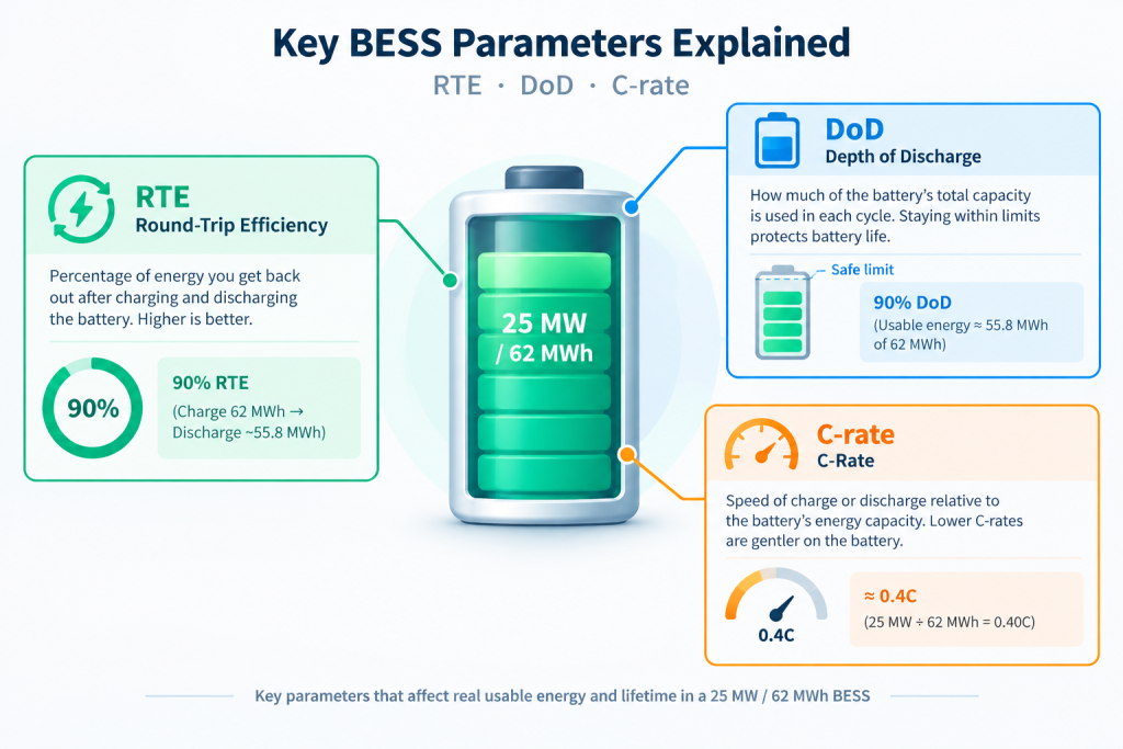
Modern lithium-ion BESS systems typically achieve 88–94% round-trip efficiency. For every 100 kWh charged into the battery, only 88–94 kWh can be discharged. In our 62 MWh example, a 90% RTE means the usable discharged energy is closer to 55.8 MWh after accounting for conversion losses. Engineers must include RTE when calculating how much solar energy can actually be shifted.
Depth of Discharge (DoD)
Battery warranties usually limit the recommended daily depth of discharge to 80–90% of nameplate capacity to protect cycle life. Operating a 62 MWh system at 90% DoD yields approximately 55.8 MWh of usable energy per cycle. Deeper cycling accelerates degradation and may void warranties.
C-Rate
C-rate describes how fast the battery is charged or discharged relative to its energy capacity. A 25 MW / 62 MWh system operates at roughly 0.4C (25 ÷ 62 ≈ 0.40). Lower C-rates are gentler on cells, improve thermal performance, and support longer lifetimes—advantages that matter for 15- to 20-year utility projects.
These three factors—RTE, DoD, and C-rate—must be considered together during any serious utility scale battery storage sizing exercise. Ignoring them leads to optimistic energy-yield models that fail in operation.
Step-by-Step Solar BESS Calculation: Reaching 25 MW / 62 MWh
Let us walk through a realistic sizing process for a mid-sized utility-scale solar plant.
Assume a 75 MWac solar photovoltaic plant located in a region with strong midday irradiance and high evening electricity prices. The developer wants the BESS to:
- Capture a portion of midday clipped energy
- Shift energy into the evening peak window
- Provide limited capacity firming and ramp-rate control
- Stay within the existing grid interconnection capacity
Power sizing (25 MW)
The interconnection agreement allows an additional 25 MW of injection beyond the solar plant’s peak export. Market analysis shows that 25 MW of flexible power captures the majority of available arbitrage and capacity revenue without triggering costly network upgrades. Therefore the BESS power rating is set at 25 MW.
Energy sizing (62 MWh)
Target duration is set at approximately 2.5 hours to cover the typical evening peak period.
Base calculation: 25 MW × 2.5 h = 62.5 MWh
After applying conservative assumptions (90% RTE and 90% DoD), the nameplate energy capacity is rounded to 62 MWh. This provides a practical buffer for auxiliary loads (HVAC, BMS, lighting) that typically consume 1–2% of system capacity.
The resulting 25MW BESS with 62 MWh energy capacity delivers a balanced solution: sufficient power for meaningful grid services and enough energy duration for valuable solar shifting, while remaining capital-efficient.
Solar BESS Nameplate Energy Calculator
Estimate the battery energy capacity required for a solar-plus-storage project. Adjust the power, duration, round-trip efficiency, and depth of discharge to compare preliminary sizing results.
Formula: Nameplate Energy = Power × Duration. The article example uses approximately 62 MWh as a practical preliminary reference for 25 MW / 2.5 hours.
Compare Typical BESS Sizing Scenarios
Reference configurations for preliminary comparison. Select a scenario to load its power, duration, efficiency, and DoD into the calculator.
| Scenario | Power (MW) | Duration (h) | RTE | DoD | Nameplate (MWh) | Usable Energy (approx.) | Action |
|---|---|---|---|---|---|---|---|
| Article Example (Base) | 25 | 2.5 | 90% | 90% | 62 MWh | ~50–56 MWh | |
| Conservative Sizing | 25 | 2.5 | 90% | 90% | 77.16 MWh | ~62 MWh | |
| 2-hour System | 25 | 2.0 | 90% | 90% | 50 MWh | ~40–45 MWh | |
| 4-hour System | 25 | 4.0 | 90% | 90% | 100 MWh | ~80–90 MWh | |
| Higher Efficiency Case | 25 | 2.5 | 94% | 90% | 59 MWh | ~50–55 MWh |
Methodology: RTE describes energy returned relative to energy charged, while DoD describes the fraction of nameplate capacity discharged. They represent different effects. The conservative formula shown here is a simplified sizing estimate, not a substitute for a supplier's energy and performance model.
Power Conversion System (PCS) Selection and Quantity
The power conversion system is the bidirectional bridge between the DC battery racks and the AC grid. Choosing the right PCS units and quantity is a critical part of BESS sizing.
Common utility-scale PCS block sizes today range from 2.5 MW to 5 MW. For a 25 MW system, a typical configuration might use:
- Ten 2.5 MW PCS units, or
- Five 5 MW PCS units, or
- A mix that includes N+1 redundancy
Many EPCs prefer modular 2.5–3.45 MW PCS skids because they offer better partial-load efficiency, easier maintenance, and graceful degradation if one unit is offline. The PCS must also support the required grid functions—reactive power, fault ride-through, and fast frequency response—while matching the voltage and current characteristics of the battery strings.
Over-sizing the PCS slightly relative to the battery power rating can improve efficiency and provide headroom for future augmentation, but excessive oversizing wastes capital. In the 25 MW example, a well-matched PCS fleet keeps the system responsive and efficient across the full operating range.
Battery Containers, Transformers, and Site Layout
Once power and energy targets are fixed, the design moves into physical equipment counts.
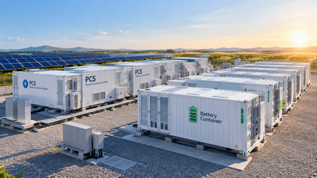
Modern battery containers typically store between 3 MWh and 5 MWh of energy in a 20-ft or 40-ft ISO form factor, depending on cell chemistry and packing density. For a 62 MWh system, engineers might specify 14–18 containers after accounting for thermal management space, fire suppression systems, and control cabinets.
Container layout must satisfy fire-safety separation distances, allow maintenance vehicle access, and minimize DC and AC cable runs. Many projects arrange containers in double rows with central aisles and place PCS skids immediately adjacent to reduce losses.
Transformer configuration is equally important. The BESS usually steps up from the PCS output voltage (typically 600–690 V) to the plant medium-voltage collection level (15–34.5 kV). Some designs share step-up transformers with the solar plant; others use dedicated BESS transformers for operational flexibility and protection isolation. The final choice depends on interconnection requirements, fault-current contributions, and cost.
BESS Equipment Sizing Comparison
Typical equipment configurations for utility-scale battery energy storage systems.
| System Size | Battery Containers | PCS Configuration | Transformer Configuration | Notes / Assumptions |
|---|---|---|---|---|
| 25 MW / 62 MWh | 15–16 | 10 × 2.5 MW or 5 × 5 MW |
2 × 12.5 MVA or 1 × 25 MVA |
~4 MWh per container; ~2.5-hour duration |
| 50 MW / 100 MWh | 24–26 | 20 × 2.5 MW or 10 × 5 MW |
2 × 25 MVA or 4 × 12.5 MVA |
Scaled-up system; ~2-hour duration |
| 100 MW / 200 MWh | 48–52 | 40 × 2.5 MW or 20 × 5 MW |
4 × 25 MVA or 2 × 50 MVA |
Scaled-up system; ~2-hour duration |
Note: Estimates assume approximately 3.8–4.2 MWh per battery container. PCS and transformer configurations are illustrative. Final sizing depends on usable energy requirements, power factor, system losses, redundancy, site layout, and applicable safety requirements.
Grid Connection and Compliance Considerations
A correctly sized BESS is useless if it cannot connect to the grid or meet local grid codes. Key interface points include:
- Point of interconnection capacity and available headroom
- Protection relays and anti-islanding requirements
- SCADA integration and remote dispatch capability
- Compliance with frequency response, voltage control, and ramp-rate limits
In many markets the BESS must demonstrate the ability to provide primary frequency response within seconds and sustain it for the required duration. The 2.5-hour energy capacity of our example system comfortably supports these services while still prioritizing energy shifting.
Early engagement with the utility or independent system operator is essential. Interconnection studies often reveal constraints that feed back into the MW and MWh decisions—another reason iterative BESS sizing is preferred over one-shot calculations.
Practical Lessons for EPCs, Developers, and Owners
Several practical takeaways emerge from the 25 MW / 62 MWh example:
- Start with clear use-case priorities (arbitrage, capacity, ancillary services, or solar firming). These drive duration more than any other factor.
- Always derate nameplate energy for RTE, DoD, and auxiliary consumption.
- Modular PCS and container designs simplify future augmentation when degradation or market changes require additional capacity.
- Total installed cost is sensitive to both power and energy; optimizing one without the other rarely yields the lowest levelized cost of storage.
- Documentation and transparent assumptions make bankability reviews far smoother.
Common pitfalls include ignoring HVAC loads, selecting an aggressive DoD that shortens warranty life, and failing to reserve interconnection capacity for the storage system.
Putting It All Together
The 25 MW / 62 MWh configuration demonstrates how thoughtful utility scale battery storage sizing balances technical performance, market opportunity, and capital discipline. By clearly separating power and energy requirements, applying realistic efficiency and depth-of-discharge factors, and translating those numbers into PCS units, containers, transformers, and grid interfaces, project teams can move from concept to bankable design with confidence.
This case study is intended as a practical companion to broader methodology. For a full framework covering every variable—from market analysis through lifetime degradation modeling—explore our other article: How to Size BESS for Utility-Scale Solar Plants: MW, MWh, Duration and PCS Guide.
Accurate solar-plus-storage sizing is both a science and an art. When done well, it unlocks higher project returns, stronger grid support, and a more resilient clean-energy system. If you are evaluating a similar 25MW BESS or scaling the approach to a larger plant, the principles outlined here will help you ask the right questions and build a solution that performs for decades.