
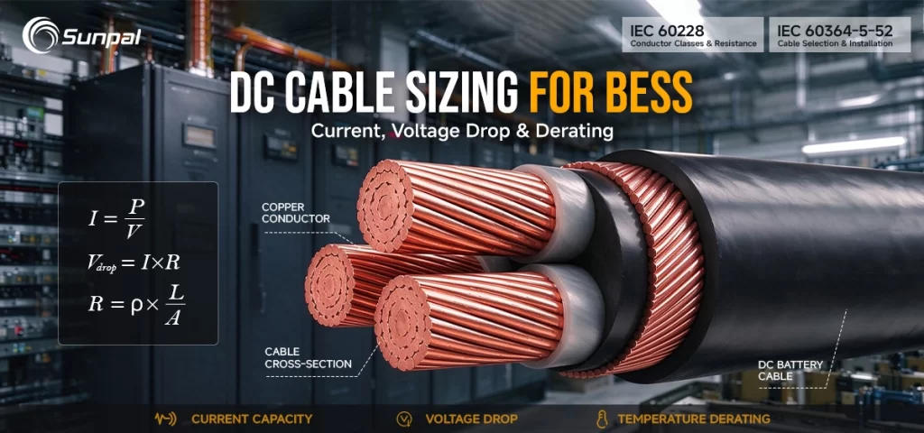
Battery energy storage systems (BESS) have become a cornerstone of modern solar energy projects. Whether paired with utility-scale solar farms or supporting commercial and industrial solar installations, these systems rely on reliable DC cabling to move power efficiently and safely between battery racks and power conversion systems (PCS). Get the cable sizing wrong, and you risk excessive heat, energy losses, nuisance trips, or even safety hazards. Get it right, and you unlock higher efficiency, longer equipment life, and better project returns.
This guide details the practical process for selecting DC cables for energy storage systems, focusing on three critical factors—current, voltage drop, and derating—to provide clear, actionable guidance based on real-world applications.
Why Proper DC Cable Sizing Matters in Solar-Plus-Storage Projects
In a typical solar-plus-storage configuration, DC cables carry high continuous currents at voltages that commonly range from 600 V to 1,500 V. Unlike AC circuits, DC circuits lack the natural zero-crossing that helps extinguish arcs, and battery systems can deliver substantial fault currents. Undersized cables create hotspots, accelerate insulation aging, and reduce the usable capacity of the energy storage system. Oversized cables inflate costs and complicate installation inside tight battery containers or outdoor skids.
Industry experience shows that voltage drop and thermal derating are frequently underestimated during early design stages. A well-sized DC cable network protects performance across the full battery voltage window, supports accurate state-of-charge management, and helps the project meet grid-code and insurance requirements.
BESS DC Cable Architecture & Electrical Connections
A technical overview of battery-side DC connections, power conversion and grid interconnection in a solar-plus-storage system.
Battery Containers & Racks
Battery modules are assembled into racks and connected through the battery-side DC distribution system. BMS monitoring, rack protection and isolation devices form part of the overall electrical architecture.
Determine conductor ampacity from maximum operating current, installation method and applicable electrical standards.
Evaluate conductor resistance and cable length to control voltage drop and associated power losses.
Consider ambient temperature, cable grouping, enclosure conditions and installation-specific correction factors.
Understanding Design Current in Battery Energy Storage Systems
The starting point for any cable sizing exercise is the design current. In BESS applications this value is rarely a single fixed number.
Designers must consider:
- Continuous operating current based on the maximum sustained discharge or charge rate
- Peak currents during high C-rate operation or grid-support functions
- Short-circuit contributions from the battery bank itself
- Future expansion or redundancy margins
A practical approach begins with the PCS DC input rating and the battery string configuration. For example, a 1.5 MW PCS operating at a nominal 1,000 V DC may see continuous currents in the range of 1,500–1,800 A depending on the exact voltage window. Battery modules or racks often specify both continuous and short-time current limits; the higher of these values, adjusted for system architecture, becomes the baseline.
Many solar companies apply a safety factor of 1.25 for continuous current when selecting conductor ampacity, consistent with established electrical codes. Short-circuit withstand must also be verified against the maximum prospective fault current and the clearing time of upstream DC protection devices.
Typical PCS Current Ranges
Keeping Voltage Drop Under Control
Voltage drop is one of the most common performance limiters in longer DC cable runs. Excessive drop reduces the voltage available at the PCS terminals, narrows the usable battery operating window, and wastes energy as heat.
For most BESS projects, designers target a total round-trip voltage drop of 1–3 % under continuous full load. Tighter limits (around 1 %) are preferred for long outdoor runs or systems operating near the edges of the battery voltage range. The basic DC voltage-drop formula is straightforward:
where ( I ) is current, ( R ) is conductor resistance per unit length (temperature-corrected), and ( L ) is one-way length. The factor of 2 accounts for the outgoing and return paths.
Resistance values must be taken at the expected operating temperature, not the 20 °C or 25 °C catalog figure. Copper and aluminum conductors both see noticeable resistance increases at elevated temperatures. Manufacturer data sheets and standards such as IEC 60228 provide the necessary correction factors.
In practice, voltage drop often forces an increase in conductor cross-section beyond the minimum required for ampacity alone—especially when battery containers are located more than 30–50 meters from the PCS. Aluminum conductors can be an economical alternative for longer runs, provided terminations and jointing practices are carefully managed.
Voltage Drop vs. Cable Length and Cross-Section
Copper conductors · 1,000 A continuous current · 1,000 V nominal
| Length (m) |
120 mm² | 150 mm² | 185 mm² | 240 mm² | 300 mm² | 400 mm² |
|---|---|---|---|---|---|---|
| 10 m | 3.1 V0.31% | 2.5 V0.25% | 2.0 V0.20% | 1.5 V0.15% | 1.2 V0.12% | 0.9 V0.09% |
| 20 m | 6.1 V0.61% | 4.9 V0.49% | 4.0 V0.40% | 3.0 V0.30% | 2.4 V0.24% | 1.9 V0.19% |
| 30 m | 9.2 V0.92% | 7.4 V0.74% | 6.0 V0.60% | 4.5 V0.45% | 3.6 V0.36% | 2.8 V0.28% |
| 50 m | 15.3 V1.53% | 12.3 V1.23% | 9.9 V0.99% | 7.5 V0.75% | 6.0 V0.60% | 4.7 V0.47% |
| 75 m | 23.0 V2.30% | 18.5 V1.85% | 14.9 V1.49% | 11.3 V1.13% | 9.0 V0.90% | 7.1 V0.71% |
| 100 m | 30.6 V3.06% | 24.6 V2.46% | 19.8 V1.98% | 15.1 V1.51% | 12.0 V1.20% | 9.4 V0.94% |
Mastering Derating Factors for Real-World Conditions
Catalog ampacity ratings assume idealized conditions that rarely exist on a solar or BESS site. Derating factors adjust the allowable current for actual installation environments. The most influential factors include:
- Ambient temperature (especially inside battery containers or under direct solar radiation)
- Cable grouping and mutual heating
- Installation method (cable tray, conduit, free air, buried, or enclosed)
- Altitude
- Insulation type and temperature rating
Multiple factors are applied multiplicatively. A cable rated 400 A in free air at 30 °C may be limited to well under 300 A once grouping, elevated ambient temperature, and tray installation are taken into account. Overlooking these reductions is a frequent cause of field problems.
For outdoor BESS installations, solar radiation can raise cable surface temperatures significantly. In hot climates or high-altitude sites, additional margins are prudent. Inside containers, forced-air or liquid cooling systems help, but designers should still base calculations on the worst-case ambient temperature specified by the battery supplier.
Standards such as IEC 60364, IEC 60502, and relevant sections of the NEC provide structured derating tables. Manufacturer-specific tables for flexible or high-temperature cables often used in BESS should be consulted whenever available.
Cable Derating Analysis
Evaluate the combined impact of ambient temperature, cable grouping and installation conditions on cable current-carrying capacity.
Three-Stage Correction Process
Each factor contributes to the final cable ampacity calculation.
Engineering Calculation Engine
LIVE CALCULATIONA Practical Step-by-Step Sizing Workflow
Successful projects follow a repeatable process rather than relying on rules of thumb:
- Establish the maximum continuous and short-time design currents, including margins.
- Select a preliminary conductor size from ampacity tables for the chosen insulation and installation method.
- Apply all relevant derating factors and verify the adjusted ampacity still exceeds the design current.
- Calculate voltage drop at the design current and maximum expected conductor temperature. Increase size if necessary.
- Confirm short-circuit thermal withstand for the expected fault duration.
- Review mechanical strength, bending radius, termination compatibility, and cost.
- Document assumptions and obtain review from a qualified electrical engineer.
A simplified worked example illustrates the process. Consider a 2 MW / 4 MWh BESS with a 1,200 V nominal DC bus and 50 m one-way cable length between containers and PCS. Continuous current is approximately 1,700 A. After applying temperature and grouping derating, a 2 × 300 mm² copper or equivalent aluminum conductor per polarity may be required to satisfy both ampacity and a 2 % voltage-drop target. Exact results depend on the precise cable type and installation details.
Preliminary vs. Final Cable Size
2 MW BESS · Copper Conductors · 1,700 A · 1,200 V DC
Preliminary Selection
After Derating
Final Selection
Example conditions: 1,700 A continuous current · 1,200 V DC · 50 m one-way cable length · ≤ 2% target voltage drop. Approximate illustrative values. Verify against actual cable datasheets and project-specific installation conditions.
Material Choices, Installation Best Practices, and Emerging Trends
Copper remains the default for most medium-length BESS DC circuits because of its superior conductivity and easier terminations. Aluminum is increasingly used for longer runs or very high-current applications where weight and cost matter. Modern cable constructions often feature XLPE or EPR insulation, low-smoke halogen-free sheathing, and enhanced fire performance to meet container and building requirements.
Best practices include clear polarity identification, proper torque on terminations, adequate support and strain relief, and accessibility for future thermographic inspection. Many operators now specify online temperature monitoring or periodic resistance checks as part of the operations and maintenance plan.
Looking ahead, the industry continues to move toward higher DC voltages (1,500 V and above), pre-fabricated plug-and-play cable solutions, and greater use of digital design tools that model thermal and electrical performance simultaneously. These trends make rigorous early-stage cable sizing even more valuable.
Common Pitfalls and How to Avoid Them
Even experienced teams occasionally encounter issues. The most frequent include:
- Using AC ampacity tables without DC-specific adjustments
- Ignoring the cumulative effect of multiple derating factors
- Calculating voltage drop at ambient rather than operating temperature
- Selecting cables that meet electrical requirements but fail mechanical or fire-performance specifications
- Leaving insufficient margin for future capacity increases
Early collaboration between the battery supplier, PCS manufacturer, cable vendor, and electrical designer prevents most of these problems. Requesting detailed cable datasheets and verified resistance values at elevated temperature is essential.
Conclusion: Building Reliable and Efficient Solar Energy Storage Systems
Correct DC cable sizing for BESS is not a minor detail—it is a foundational element of system safety, efficiency, and long-term performance. By carefully evaluating design current, controlling voltage drop, and applying realistic derating factors, solar companies and project developers can avoid costly redesigns and operational surprises.
The process rewards discipline: start with accurate load data, apply standards-based methods, verify with calculation and experience, and document every assumption. When these steps are followed, the DC cabling becomes an enabler rather than a constraint, supporting the reliable delivery of clean, dispatchable power from solar-plus-storage assets.
As battery energy storage systems continue to scale alongside solar generation, attention to these fundamentals will remain a hallmark of high-quality project execution. Ready to optimize your next BESS project? Contact the Sunpal team today for expert guidance on DC cable selection and system design.
Frequently Asked Questions (FAQ)
1. What is the recommended voltage drop limit for DC cables in a BESS?
Most designers target a total round-trip voltage drop of 1–3 % under continuous full load. A tighter limit of around 1 % is often preferred for longer cable runs or systems that operate near the edges of the battery voltage window to protect efficiency and PCS performance.
2. How do I calculate voltage drop for BESS DC cables?
Use the standard DC formula: Voltage drop = Current × Resistance per unit length × One-way length × 2. Always correct the conductor resistance for the expected operating temperature, not the catalog value at 20 °C or 25 °C. Manufacturer data sheets and standards such as IEC 60228 provide the necessary temperature correction factors.
3. What are the most important derating factors for DC cables in battery energy storage systems?
The key factors are ambient temperature (especially inside containers or under solar radiation), cable grouping, installation method (tray, conduit, free air, etc.), altitude, and insulation temperature rating. These factors are normally applied multiplicatively to the base ampacity.
4. Should I use copper or aluminum cables for BESS DC circuits?
Copper is the most common choice for medium-length runs because of its higher conductivity and simpler terminations. Aluminum can offer cost and weight advantages on longer runs or very high-current circuits, provided terminations are properly designed and installed.
5. How does temperature affect DC cable sizing in solar-plus-storage projects?
Higher ambient or operating temperatures increase conductor resistance and reduce ampacity. Inside battery containers or in hot climates, significant derating is often required. Always base calculations on the worst-case temperature specified by the battery and cable manufacturers.
6. What standards should I follow when sizing DC cables for BESS?
Common references include IEC 60364, IEC 60502, IEC 60228, and relevant sections of the NEC (particularly Articles 310, 690, and 706). Always cross-check with local grid codes and the specific requirements of the battery and PCS suppliers.
7. Can I use AC cable ampacity tables for DC BESS applications?
It is not recommended. While some principles overlap, DC circuits have different thermal and fault-current characteristics. Use DC-specific data or confirmed manufacturer ratings whenever possible, and apply appropriate derating for the actual installation conditions.
8. How much safety margin should I add when sizing BESS DC cables?
Many solar companies apply a 1.25 multiplier to the continuous design current when selecting ampacity, in line with established electrical practices. Additional margin may be included for future expansion, redundancy, or unusually harsh site conditions.