
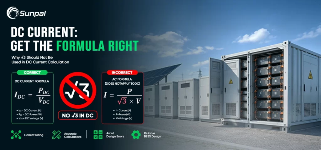
In the fast-growing world of solar energy, precision in electrical calculations can mean the difference between a high-performing, safe solar PV system and one plagued by inefficiencies, overheating cables, or failed inspections. One of the most persistent yet preventable errors occurs when designers, installers, or engineers apply the square root of three () to direct current (DC) calculations. This factor belongs exclusively to balanced three-phase alternating current (AC) systems. Using it on the DC side of a solar installation—whether for PV string current, battery energy storage system (ESS) sizing, cable ampacity, or voltage drop—produces incorrect results that can compromise safety, increase costs, and reduce system reliability.
This article explains exactly why has no place in DC current calculation, walks through the correct formulas used every day in solar design, highlights real-world mistakes common in the industry, and provides practical guidance for solar companies, EPCs, and installers. By the end, you will have a clear framework for keeping DC and AC calculations strictly separate in every solar project.
The Hidden Cost of a Simple Math Mistake in Solar PV Systems
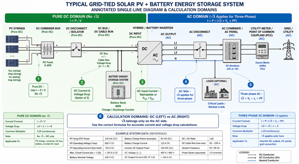
Solar professionals work daily with both DC and AC electricity. Photovoltaic modules generate DC power. Batteries store and discharge DC energy. Hybrid inverters and string inverters convert that power to AC for the grid or loads. The boundary between these domains is where formula errors most often appear.
Imagine sizing DC cables for a large commercial solar array or calculating the maximum current into a battery energy storage system. If someone accidentally inserts into the current formula—treating the DC circuit as if it were three-phase AC—the calculated amperage will be roughly 42% too low (or too high, depending on how the formula is rearranged). The result can be undersized conductors that overheat under continuous solar irradiance, oversized and unnecessarily expensive cable runs, incorrect fuse or breaker selection, or voltage-drop percentages that fail to meet project specifications.
These errors are not theoretical. They surface during plan review, commissioning, or worse, after years of operation when thermal stress finally causes a failure. In an industry focused on bankability, long-term performance, and safety, eliminating this mix-up is essential.
Where Actually Comes From: A Quick Refresher on Three-Phase Power
To understand why must stay out of DC calculations, it helps to recall its legitimate origin. In a balanced three-phase AC system, the three voltages are displaced by 120 electrical degrees. The relationship between line-to-line voltage and phase (line-to-neutral) voltage is:
The total three-phase real power is given by the well-known formula:
or, rearranged for current:
The factor arises purely from the vector (phasor) addition of the three phase-shifted waveforms. It has no equivalent in a steady DC circuit, where voltage and current are constant in magnitude and direction (apart from normal ripple in practical systems). There is no phase angle, no reactive power component in the same sense, and no three-phase geometry.
Single-phase AC sits in between: . Only when three balanced phases are present does appear.
Three-Phase Geometry
The Correct Way to Calculate Current on the DC Side of a Solar System
On the DC side of any solar PV system or energy storage system, the relationships remain fundamentally simple:
These formulas apply to PV string current (using Imp or the higher Isc value as required by code), maximum circuit current for conductor and overcurrent protection sizing, battery charge or discharge current, and DC bus calculations.
Voltage drop on DC circuits uses the round-trip path:
or the equivalent form using resistivity, length, and cross-sectional area. Contrast this with the three-phase AC voltage-drop formula, which includes a multiplier. Applying the AC version to a DC PV run will again produce incorrect results.
In solar design practice, additional code-driven multipliers appear—most commonly the 125% continuous-duty factor applied to PV circuit current under standards such as the National Electrical Code (NEC) Article 690. These factors address continuous generation under sunlight and temperature effects; they are not substitutes for and should never be confused with it.
When working with inverter DC input current, start from the inverter's continuous input current rating on the nameplate or calculate from DC power and DC voltage after accounting for efficiency and DC/AC ratio. Do not reverse-engineer from the AC output power using a three-phase formula and then apply .
How Creeps into Solar DC Calculations—and Why It Happens So Often
Several everyday situations in solar project workflows invite the error:
- An engineer copies a three-phase AC spreadsheet template and reuses it for DC string or battery calculations without removing the term.
- Cable-sizing software defaults to a three-phase setting while the user is working on the PV DC side or battery DC side.
- Someone calculates expected current from an inverter's AC power rating and accidentally inserts the three-phase formula when determining DC input current or DC cable size.
- Training materials or older reference sheets that focus heavily on utility AC systems are applied without adaptation to the DC-dominant solar environment.
- Hybrid and DC-coupled systems blur the mental boundary between domains, increasing the chance of formula crossover.
The consequences scale with system size. On a residential solar installation the error may be modest. On a multi-megawatt commercial or utility-scale solar plant with long DC cable runs, parallel strings, and large battery energy storage systems, the impact on material cost, voltage drop, thermal performance, and inspection outcomes becomes significant.
79.2 A lower design current
Side-by-Side Formulas and Practical Solar Examples
Keep these formulas visible on every design desk or software dashboard:
- DC (PV strings, batteries, DC bus):
- Single-phase AC:
- Balanced three-phase AC:
Example 1 – PV Array DC Current
A solar array section produces 120 kW at 800 V DC under design conditions.
Correct current: A.
Incorrectly inserting yields approximately 86.6 A—dangerously low for cable and protection sizing.
Example 2 – Battery Energy Storage Charge Current
A battery system charges at 50 kW on a 400 V DC bus.
Correct current: A.
Using the three-phase formula produces a substantial underestimation that could lead to undersized conductors between the inverter/charger and the battery.
Example 3 – Voltage Drop on a Long DC Run
For a 100-meter one-way DC cable carrying 150 A with a given resistance, the DC voltage-drop formula uses the factor of 2. Substituting the three-phase version produces a completely different (and incorrect) percentage drop, potentially causing the designer to select the wrong conductor size or to fail project voltage-drop limits.
These examples illustrate why solar companies and customers searching for accurate “solar cable sizing,” “PV string current calculation,” or “DC current in solar systems” need clear, domain-specific guidance.
A side-by-side comparison across residential, commercial and utility-scale solar systems showing how incorrectly inserting √3 into a DC calculation systematically underestimates current.
| Scale | Example System | Power | DC Voltage |
Correct DC Current |
Incorrect √3 Current |
Absolute Difference |
Error |
|---|---|---|---|---|---|---|---|
| Residential | Small rooftop system | 8 kW | 400 V | 20.0 A 8,000 ÷ 400 | 11.5 A 8,000 ÷ (√3 × 400) | −8.5 A | 42.3% |
| Residential | Typical home system | 12 kW | 450 V | 26.7 A 12,000 ÷ 450 | 15.4 A 12,000 ÷ (√3 × 450) | −11.3 A | 42.3% |
| Residential | Larger residential | 20 kW | 500 V | 40.0 A 20,000 ÷ 500 | 23.1 A 20,000 ÷ (√3 × 500) | −16.9 A | 42.3% |
| C&I | Small commercial | 100 kW | 600 V | 166.7 A 100,000 ÷ 600 | 96.2 A 100,000 ÷ (√3 × 600) | −70.5 A | 42.3% |
| C&I | Mid-size commercial | 250 kW | 800 V | 312.5 A 250,000 ÷ 800 | 180.4 A 250,000 ÷ (√3 × 800) | −132.1 A | 42.3% |
| C&I | Large C&I / industrial | 500 kW | 1,000 V | 500.0 A 500,000 ÷ 1,000 | 288.7 A 500,000 ÷ (√3 × 1,000) | −211.3 A | 42.3% |
| Utility | Small utility block | 2 MW | 1,200 V | 1,666.7 A 2,000,000 ÷ 1,200 | 962.3 A 2,000,000 ÷ (√3 × 1,200) | −704.4 A | 42.3% |
| Utility | Medium utility array section | 5 MW | 1,500 V | 3,333.3 A 5,000,000 ÷ 1,500 | 1,924.5 A 5,000,000 ÷ (√3 × 1,500) | −1,408.8 A | 42.3% |
| Utility | Large utility section | 10 MW | 1,500 V | 6,666.7 A 10,000,000 ÷ 1,500 | 3,849.0 A 10,000,000 ÷ (√3 × 1,500) | −2,817.7 A | 42.3% |
Inserting √3 into a DC current calculation consistently underestimates the actual current, potentially resulting in undersized conductors, excessive voltage drop and thermal risk.
Best Practices Every Solar Professional Should Follow
1. Identify the domain first. Before any calculation, confirm whether the circuit is pure DC (modules, strings, combiners, DC optimizers, batteries, DC bus), single-phase AC, or three-phase AC.
2. Prefer nameplate and datasheet values. Use module Imp and Isc, inverter continuous DC input current, and battery continuous charge/discharge ratings directly whenever possible.
3. Maintain separate calculation environments. Keep distinct spreadsheet tabs, software projects, or templates labeled “DC Side – No ” and “AC Side.”
4. Apply code factors correctly. Continuous-load multipliers, temperature corrections, and conduit fill adjustments are independent of the question. Apply them after the correct base current is established.
5. Review hybrid and DC-coupled designs with extra care. These architectures increase the number of DC current paths and therefore the opportunity for formula crossover.
6. Train teams and document decisions. Include a short module on “DC versus AC current calculation” in installer and designer training. Require a quick peer check on critical current and cable-sizing calculations.
Following these steps protects system performance, supports smooth permitting and interconnection, and reduces the risk of costly field changes.
Looking Ahead: Cleaner Calculations for a More Electrified Future
As solar PV systems grow larger, DC voltages rise, battery energy storage becomes standard, and hybrid architectures proliferate, the volume of DC current calculations will only increase. The industry's reputation for reliability depends on getting the fundamentals right every time. remains an indispensable tool for three-phase AC work—grid interconnection, three-phase inverters, and utility-side equipment. It simply has no role in the DC domain that begins at the solar modules and often extends through the battery system.
By treating DC current calculation as the straightforward relationship it is, solar companies deliver safer installations, more accurate material take-offs, better voltage-drop performance, and higher confidence among customers and financiers. The next time a spreadsheet, software default, or mental shortcut tempts the insertion of into a DC formula, pause and remove it. The solar system—and everyone who relies on it—will be better for the discipline.
Accurate DC current calculation is not glamorous, but it is foundational. In an industry measured by decades of reliable energy production, mastering this distinction is one of the highest-leverage habits a solar professional can adopt.