
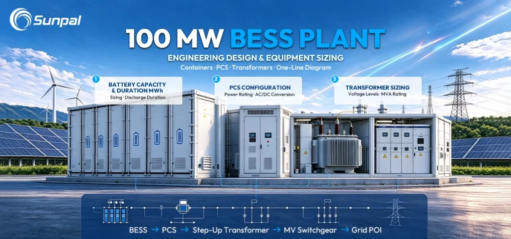
Utility-scale solar projects are no longer complete without storage. As solar farms grow larger and grid operators demand firmer, more dispatchable renewable energy, a well-engineered 100MW battery energy storage system has become a critical partner to photovoltaic plants. Designing such a system requires far more than selecting batteries. It demands a clear understanding of full BESS architecture—from the plant interconnection all the way down to the individual cell—along with precise integration of containers, power conversion systems, transformers, and control layers.
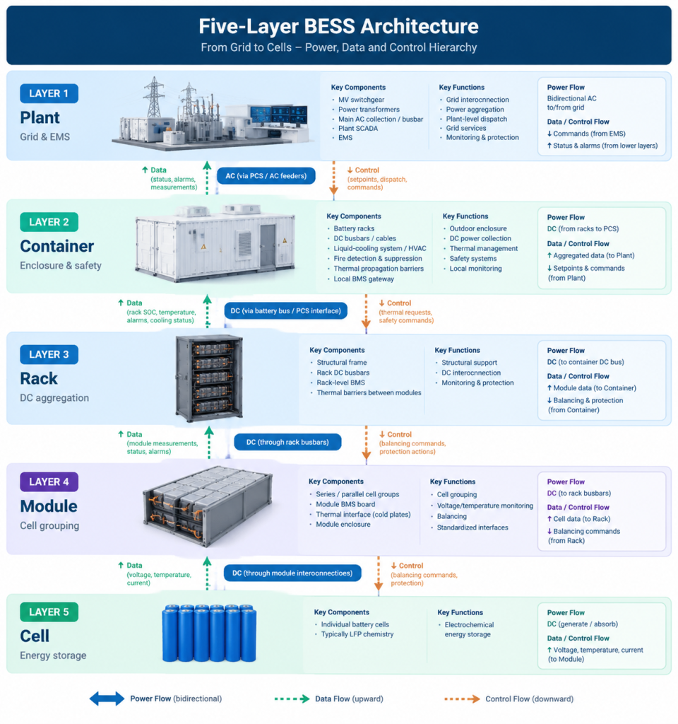
This guide walks through practical 100MW BESS plant design with a focus on containers, PCS, transformers, and the one-line diagram. We organize the discussion around the proven five-layer hierarchy: Plant → Container → Rack → Module → Cell. Along the way we explain the roles of key battery energy storage system components including PCS, MV switchgear, transformers, SCADA, EMS, BMS, HVAC or liquid-cooling systems, fire suppression, busbars, and thermal propagation barriers. The goal is to give solar developers, EPCs, and asset owners a clear, actionable view of robust BESS system integration.
Why 100MW BESS Architecture Matters for Modern Solar Projects
Solar companies and their customers increasingly search for reliable ways to pair photovoltaic generation with storage that can deliver capacity firming, energy shifting, and ancillary services. A 100MW BESS represents a common utility-scale building block—large enough to move the needle on project economics yet modular enough for phased deployment. Success hinges on thoughtful BESS architecture and disciplined system integration rather than simply stacking containers.
When the architecture is clear, every battery energy storage system component has a defined role, thermal and safety risks are controlled, and the plant can respond accurately to grid signals. When it is not, projects face higher losses, longer commissioning times, and greater operational risk. The five-layer model provides that clarity.
Plant-Level View: Laying Out a 100MW BESS for Solar-Plus-Storage Success
At the plant level the BESS must interconnect cleanly with the grid or with an adjacent solar farm, manage high power flows, and present a single controllable asset to the offtaker or system operator.
A typical 100MW / 200–400MWh configuration might include dozens of battery containers, multiple PCS units clustered in skids or dedicated enclosures, medium-voltage collection, and one or more step-up transformers. Power flows from the DC side of the containers through the PCS, into the AC collection system, through MV switchgear, and finally across the main power transformers to the point of interconnection.
Key plant-level components and their roles include:
- Medium-voltage switchgear that provides protection, isolation, and sectionalizing so that individual PCS clusters or transformers can be taken offline without shutting down the entire plant.
- Power transformers that step voltage up to transmission or sub-transmission levels, provide galvanic isolation, and are sized for continuous rating plus temporary overload capability required by many grid codes.
- The main AC busbar or cable collection system that aggregates output from multiple PCS units with low losses and adequate short-circuit withstand.
- Plant SCADA and the Energy Management System (EMS) that orchestrate dispatch, monitor state of charge across the fleet, execute grid services, and interface with the utility or market operator.
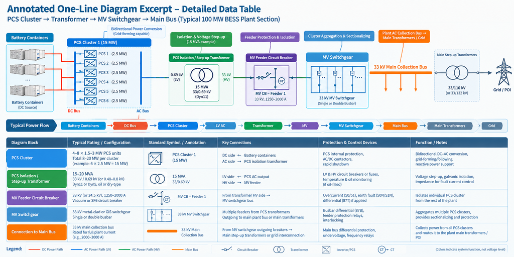
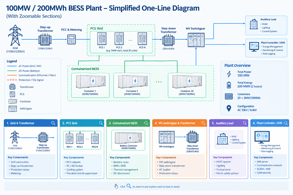
A clear one-line diagram is indispensable at this stage. It shows the electrical relationships, protection zones, metering points, and auxiliary supplies in a single view that engineers, protection specialists, and commissioning teams can all reference. We return to a practical example of such a diagram later.
For solar-plus-storage projects the plant-level design must also consider coupling method (AC-coupled is most common for large existing or co-located solar farms), shared interconnection capacity, and coordinated ramp-rate control so that the combined solar-plus-BESS resource behaves predictably.
Inside the BESS Container: The Workhorse of Utility-Scale Storage
The BESS container is the fundamental outdoor building block. Modern liquid-cooled containers typically house several battery racks, integrated thermal management, fire detection and suppression, local controls, and DC collection.
A well-designed container prioritizes safety, maintainability, and thermal uniformity. Liquid cooling loops circulate coolant through cold plates or cooling plates attached to modules, removing heat far more effectively than air cooling alone in high-energy-density packs. Backup HVAC or hybrid systems handle extreme ambient conditions or provide redundancy. Thermal propagation barriers—whether intumescent materials, specialized insulation, or physical separations—limit the spread of a thermal event from one module or rack to another. Fire suppression systems (often clean-agent or water-mist based, depending on local codes and battery chemistry) activate on early detection signals from smoke, gas, or temperature sensors.
DC busbars or carefully engineered cable systems collect current from the racks and route it to external disconnects or directly toward the PCS. Local BMS gateways aggregate rack data and communicate upward. Auxiliary power, communications, and cooling interfaces connect the container to the broader plant.
At 100MW scale, standardization of container design pays large dividends in procurement speed, spare-parts logistics, and construction sequencing. Containers must also meet transportation constraints, IP ratings for outdoor use, and site-specific structural requirements for wind and seismic loads.
This container-level focus is central to reliable BESS system integration. Solar customers evaluating suppliers increasingly ask detailed questions about thermal management and fire-safety design because these factors directly affect long-term performance and bankability.
| Performance Metric | Air-Cooled Containers | Liquid-Cooled Containers | Advantage |
|---|---|---|---|
| Temperature Uniformity | ΔT typically 8–15 °C across modules/cells | ΔT typically 2–5 °C, often below 3 °C | Liquid-cooled |
| Energy Density | 150–220 kWh/m³; larger air channels and fans can limit packing density | 250–350+ kWh/m³; compact cold-plate designs can enable higher density | Liquid-cooled (20–50% higher potential) |
| Auxiliary Load | 2.5–5% of rated power; fan consumption rises with cooling demand | 1–2.5% of rated power; pumps and fans typically consume less energy | Liquid-cooled (typically 30–50% lower) |
| Suitability for High-Ambient Solar Sites | More limited at high ambient temperatures; derating may be required above 35–40 °C | Well suited to hot climates when the chiller and heat-rejection system are properly specified | Liquid-cooled |
| Maximum Ambient Operating Temperature | Typically 40–45 °C; derating may occur at elevated temperatures | Typically 45–55 °C for appropriately rated systems | Liquid-cooled |
| Impact on Battery Cycle Life | Higher temperature gradients may accelerate uneven cell degradation | More uniform temperatures can help reduce uneven aging | Liquid-cooled* |
| Noise Level | Multiple fans may produce higher noise levels | Smaller fans and pumps; actual noise depends on system design | Often liquid-cooled |
| Maintenance Complexity | Simpler maintenance involving fans, filters and airflow paths | Additional coolant loops, pumps, leak detection and fluid maintenance | Air-cooled |
Note: Values are indicative industry ranges for utility-scale LFP BESS. Actual performance depends on equipment specifications, ambient conditions, operating profiles and measurement boundaries. Energy density and auxiliary-load comparisons should be verified against comparable manufacturer data. *Cooling type alone does not determine battery cycle life or safety.
From Rack to Module to Cell: Building Reliability from the Ground Up
Inside each container the hierarchy continues.
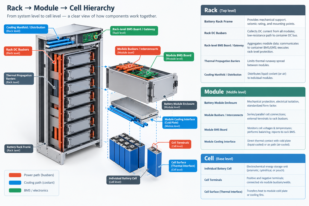
Racks provide structural support, DC electrical interconnection via busbars, and mounting for rack-level BMS monitoring. They also host thermal propagation barriers that isolate groups of modules. Proper busbar design balances low resistance for efficiency with adequate cross-section for fault currents and ease of maintenance.
Modules group cells in series and parallel combinations, incorporate module-level monitoring and balancing, and present a standardized thermal interface to the cooling system. The quality of thermal contact between modules and cold plates strongly influences temperature gradients and therefore cycle life.
At the foundation sit the cells themselves—most commonly lithium iron phosphate (LFP) in utility-scale applications for their safety and cycle-life characteristics. Cell selection and quality determine the raw energy, power capability, and degradation trajectory that every higher layer must manage.
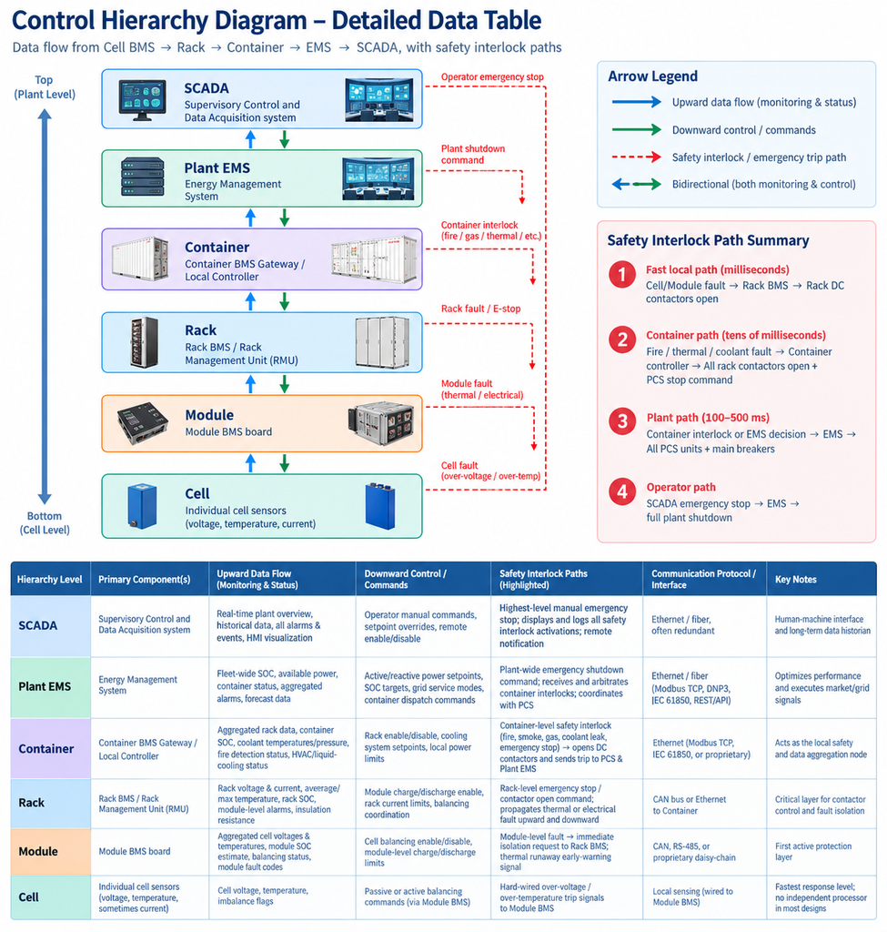
Data and protection commands flow upward: cell voltages and temperatures are monitored by the module and rack BMS, which report to the container and ultimately to the plant EMS. Understanding this chain helps solar project teams specify meaningful warranties and performance guarantees.
Power Conversion and Grid Interface: PCS, Transformers, and MV Switchgear
The Power Conversion System is the bridge between the DC battery world and the AC grid. In a 100MW plant, multiple PCS units—often in the 1–5MW range each—are paralleled. Modern PCS equipment supports both grid-following and grid-forming modes, delivers reactive power, meets fault-ride-through requirements, and executes fast frequency response when called upon.
Close coordination between the PCS, BMS, and EMS is essential. The BMS provides real-time limits based on cell conditions; the EMS sets the active and reactive power setpoints according to market or contractual obligations; the PCS executes those setpoints while protecting itself and the batteries.
Transformers step the PCS output voltage up to the collection or interconnection voltage. Key design choices include impedance (affecting short-circuit levels and voltage regulation), cooling method, and whether multiple smaller transformers or fewer larger units are preferred for redundancy. MV switchgear sits between the PCS transformers and the main interconnection transformers, providing the protection and switching necessary for selective isolation.
All of these elements appear prominently on the plant one-line diagram. Protection engineers use the diagram to set relays, calculate fault currents, and verify coordination. A clean, accurate one-line is therefore not just documentation—it is a core design and safety tool.
Control, Monitoring, and Safety: EMS, BMS, SCADA, Thermal Management, and Fire Protection
Reliable operation depends on layered controls and safety systems.
The Battery Management System operates at cell, module, and rack levels to enforce voltage, current, and temperature limits, perform balancing, and detect early signs of abnormal behavior. The Energy Management System works at plant level to optimize dispatch, manage state-of-charge targets across containers, and deliver the grid services that make solar-plus-storage projects bankable. SCADA provides the human-machine interface, alarm management, data historian, and remote access that operators need.
Thermal management—whether primarily liquid cooling with HVAC support or a hybrid approach—keeps cells within their optimal temperature window, directly influencing efficiency, degradation, and safety. Fire detection and suppression systems, combined with thermal propagation barriers, form the last line of defense. These systems must be integrated so that a detection event can trigger controlled shutdowns via the BMS and EMS while notifying plant operators through SCADA.
When all layers communicate cleanly, the BESS becomes a predictable, controllable asset that complements variable solar generation.
A Practical 100MW One-Line Diagram and Design Takeaways
Imagine a representative one-line: the utility interconnection at the top, main step-up transformers, a medium-voltage bus with several feeder breakers, each feeder serving a PCS cluster with its own isolation transformer, and then the DC side disappearing into groups of battery containers. Auxiliary transformers supply cooling skids, controls, and lighting. Metering and protection devices are shown at each major boundary.
Key takeaways for solar companies designing or procuring such a system include:
- Start with the five-layer architecture so that every battery energy storage system component has a clear owner and interface.
- Treat container design, liquid-cooling performance, and fire-safety integration as first-order decisions, not afterthoughts.
- Size PCS and transformers with both steady-state and dynamic requirements in mind.
- Demand a clear one-line diagram and supporting protection study early in the design process.
- Prioritize BESS system integration experience—how the supplier coordinates PCS, BMS, EMS, and plant SCADA often determines real-world performance more than any single component specification.
Building Bankable Solar-Plus-Storage Projects with Proven BESS Architecture
A 100MW BESS plant is a complex but manageable system when approached through a structured architecture. By breaking the design into Plant, Container, Rack, Module, and Cell layers and carefully specifying the roles of PCS, transformers, MV switchgear, controls, thermal management, and safety systems, project teams can reduce risk and improve long-term returns.
Sunpal focuses on exactly this integrated approach—container design optimized for liquid cooling, coordinated PCS/BMS/EMS operation, and practical plant-level engineering that supports utility-scale solar and storage projects. For teams ready to move from concept to detailed design, the complete reference architecture and additional technical resources are available in our Battery Energy Storage System Components: Complete BESS Architecture Guide. We also invite you to explore our utility-scale BESS solution capabilities for project-specific discussions.
Thoughtful BESS architecture turns variable solar generation into a firmer, more valuable resource. The plants that achieve this most successfully are those that treat every layer—and every interface between layers—with equal care.