
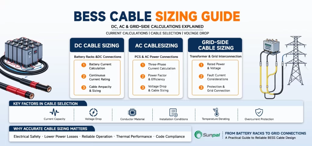
Battery energy storage systems are now central to modern solar projects. Whether paired with large-scale PV plants or deployed as standalone grid assets, a well-designed BESS depends on one often-overlooked detail: correct cable sizing. Undersized cables waste energy through heat and voltage drop, trigger nuisance trips, shorten equipment life, and in the worst cases create fire hazards. Oversized cables inflate project costs without delivering proportional value.
This guide walks through practical BESS cable sizing for the DC side, AC side, and grid side. It covers current calculation, ampacity selection, voltage-drop limits, temperature and installation derating, protection coordination, and the key standards engineers actually use. Special attention is given to a frequent and costly error: applying the three-phase √3 factor to DC circuits.
Why Proper Cable Sizing Separates Reliable Projects from Costly Headaches
In solar-plus-storage projects, the DC cables between battery racks and the power conversion system (PCS) often carry hundreds of amperes at voltages ranging from a few hundred to 1,500 V. On the AC side, the same power flows at lower current but must meet grid-code voltage and power-quality requirements. Grid-side cables then connect the plant to the transformer or point of interconnection.
Engineers who treat cable sizing as a quick table lookup frequently discover problems only after commissioning: unexpected voltage drop that forces the inverter offline early, elevated operating temperatures inside containers, or protective devices that refuse to coordinate. Correct BESS electrical design prevents these issues at the drawing-board stage.
The process follows a consistent sequence regardless of side:
- Calculate the design current (including continuous-load factors).
- Apply all relevant derating factors for temperature, grouping, and installation method.
- Select a conductor whose derated ampacity still exceeds the design current.
- Verify voltage drop (and rise where applicable) over the actual route length.
- Confirm short-circuit withstand and protection coordination.
Five-Step BESS Cable Sizing Process
Interactive engineering workflow · Calculation · Verification · Protection
Calculate Design Current
Determine the continuous current that the cable must carry under the maximum BESS operating load. Switch between DC and AC calculations to examine the corresponding design current.
I = (P × 1000 / V) × 1.25
The Foundation: Design Current Comes First
Everything starts with accurate current. For DC cable sizing for battery storage, the fundamental relationship is straightforward:
More precisely, designers use the higher of the maximum continuous charge current or discharge current, evaluated at the relevant voltage (often the minimum operating voltage for discharge to capture the highest current). A continuous-load multiplier of 1.25 is then applied in most jurisdictions, consistent with NEC treatment of ESS circuits and similar practice under IEC-based rules.
Here is the critical correction that many online calculators and even some early project documents still get wrong: do not multiply or divide by √3 on the DC side. The √3 factor appears only in three-phase AC power equations. Applying it to DC systematically under-sizes the cable. Several practicing engineers have publicly flagged this exact mistake in industry discussions; it remains one of the highest-leverage corrections an owner or EPC can make during design review.
On the AC side the √3 factor returns, as expected:
Single-phase circuits omit the √3. Power factor is taken from the PCS datasheet under the expected operating conditions.
DC-Side Cable Sizing: Battery Racks to PCS
The DC side is usually the most demanding. Modern BESS containers operate at 600–1,500 V DC to keep current manageable, yet individual rack or string currents still commonly reach 200–500 A. Low-voltage legacy systems (48 V or 125 V) produce even higher currents and are extremely sensitive to voltage drop.
Ampacity selection begins with published tables—NEC Table 310.16 (or 310.15), IEC 60364-5-52, or the newer DC-specific tables in AS/NZS 3008.1.1. Prefer 90 °C or higher XLPE or thermoset insulation. Inside battery containers, ambient temperatures can exceed 40–50 °C and cables may be bundled, so free-air ratings are rarely usable without substantial derating.
Voltage drop on DC uses the round-trip formula:
or equivalently
where (L) is the one-way length. Industry practice for battery-to-inverter runs targets 1–2 % drop; some manufacturers specify even tighter limits because voltage drop directly reduces usable energy and can push the PCS into low-voltage shutdown while the batteries still hold charge. At 48 V a 2 V drop already represents more than 4 % loss—far more painful than the same absolute drop at 1,000 V or 1,500 V.
Derating factors compound quickly. Ambient temperature correction, grouping (NEC Table 310.15(C)(1) or IEC equivalents), conduit fill, burial depth, soil thermal resistivity, and proximity to potential thermal-runaway zones all reduce allowable current. It is not unusual for the effective ampacity of a cable inside a crowded container to fall to 50–60 % of its free-air rating. Always apply the factors before selecting the final cross-section.
Protection must be coordinated with the very high prospective short-circuit current that lithium-ion batteries can deliver. Fuses or breakers are placed as close as practical to the battery source. The cable’s \(I^2t\) withstand must exceed the let-through energy of the protective device.
Example DC Cable Sizes for a 1 MW PCS
(Representative values for copper conductors, 90 °C XLPE insulation, typical BESS-container derating factor ≈ 0.75, 1.5 % voltage-drop limit)
| DC Voltage | Continuous Current (A) | Design Current (1.25×) (A) | Recommended Copper Configuration (after typical derating) | Approx. Max. One-Way Length for 1.5 % Voltage Drop (m) |
|---|---|---|---|---|
| 800 V | 1,250 | 1,563 | 5 × 300 mm² or 4 × 400 mm² parallel | 260 – 280 |
| 1,000 V | 1,000 | 1,250 | 4 × 300 mm² or 5 × 240 mm² parallel | 320 – 330 |
| 1,500 V | 667 | 833 | 3 × 300 mm² or 2 × 400 mm² parallel | 490 – 550 |
AC-Side Cable Sizing: From PCS to the Next Stage
Once power has been converted, the AC side follows more familiar three-phase rules. Design current is 1.25 times the continuous rated output of the PCS. Voltage-drop calculations now include both resistance and reactance terms, and the three-phase formula incorporates √3:
Typical targets remain 2–3 %, but many grid codes impose stricter voltage-rise limits at the point of connection. Parallel cables, if used, must be matched in length and impedance (often within 2–5 %) to avoid unequal current sharing.
Derating principles are identical to the DC side, although skin and proximity effects appear at higher currents and frequencies. Cable selection also considers harmonic content from the PCS and any filtering requirements.
Grid-Side Considerations: Connecting to the Network
Grid-side cables—whether low-voltage feeders to a main switchboard or medium-voltage runs to a transformer and POI—must satisfy both the project’s continuous power rating and the utility’s interconnection requirements. Fault levels, transformer inrush, reactive-power capability, and anti-islanding protection all influence final sizing. Longer runs make voltage drop and losses more economically significant; engineers often evaluate the lifetime cost of copper or aluminum against energy losses.
Installation methods shift toward direct burial, duct banks, or overhead lines, each with its own thermal-resistivity and ampacity tables. Coordination studies become essential so that plant protection and utility reclosers work together.

Temperature, Installation Methods, and Derating—The Quiet Project Killers
Regardless of DC, AC, or grid side, real-world conditions rarely match the base tables. Ambient temperature inside a BESS container on a summer afternoon, multiple circuits sharing a tray, cables buried in dry soil, or harnesses routed near battery modules all reduce capacity. The correct workflow multiplies every applicable factor:
Only after this reduced value is known should the engineer select the next standard cross-section that still exceeds the design current. Skipping derating is one of the most common reasons cables run hot in the field.
Fine-stranded flexible copper remains the default for DC connections inside containers because of vibration, thermal cycling, and the need for reliable terminations. Aluminum appears more often on longer AC or grid runs where cost and weight matter. In every case the insulation system must be explicitly rated for the DC or AC voltage and for the expected thermal environment.
Standards That Actually Guide BESS Electrical Design
Designers typically work from a combination of:
- NEC Articles 690 and 706 (United States)
- IEC 60364-5-52 and IEC 60287 (ampacity calculation)
- IEC 62933 series for electrical energy storage systems
- AS/NZS 3008.1.1 (including its newer DC tables) and AS/NZS 5139
- Manufacturer datasheets and local utility interconnection rules
These documents set the minimum safety floor; experienced teams often adopt tighter internal voltage-drop and temperature limits to improve long-term performance and bankability.
Summary Table of Typical Voltage-Drop Limits by Circuit Type
| Circuit Type | Typical Voltage-Drop (or Rise) Limit | Common Industry Target | Notes |
|---|---|---|---|
| PV Strings (DC) | 1 – 3 % | ≤ 1.5 – 2 % | Tighter limits improve long-term energy yield |
| Battery-to-PCS (DC) | 1 – 2 % | ≤ 1 – 1.5 % | Critical for usable capacity and avoiding low-voltage shutdown |
| PCS AC Output | 2 – 3 % (drop) / ≤ 2 % (rise) | ≤ 2 % | Voltage-rise limits at the connection point are often stricter |
| Grid Feeder / Interconnection | 3 – 5 % (total) / utility-specific | ≤ 2 – 3 % | Final limit is normally set by the network operator |
Practical Checklist and a Real-World Anchor
Before releasing drawings, confirm:
- Design current calculated correctly (no √3 on DC).
- All temperature, grouping, and installation derating factors applied.
- Selected cable ampacity still exceeds design current after derating.
- Voltage drop within project limits using actual route length (round-trip on DC).
- Protective device located near the source and coordinated with cable withstand.
- Terminal temperature ratings respected.
- Cable insulation and switchgear explicitly DC- or AC-rated as required.
For a concrete illustration of these steps applied to a multi-megawatt system, see the companion detailed sizing example for a 25 MW / 62 MWh BESS. That worked case shows how the same principles scale from a single rack to a full plant.
Closing the Loop on Safe, Efficient Storage
Correct BESS cable sizing is not glamorous, yet it directly determines whether a solar-plus-storage project delivers its modeled energy, operates within temperature limits, and passes utility witness testing the first time. By calculating current properly—especially avoiding the √3 trap on the DC side—applying realistic derating, controlling voltage drop, and coordinating protection, engineering teams remove one of the most common sources of post-commissioning surprises.
The methods outlined here are deliberately practical. They can be implemented with standard tables, a spreadsheet, and the actual route lengths measured on site. When the cables are right, the rest of the BESS electrical design has a solid foundation on which to perform for the life of the plant.
Ready to Get Your BESS Cable Design Right the First Time?
Contact Sunpal today for a free preliminary cable-sizing review, or a consultation on your specific DC, AC, and grid-side requirements. Let’s make sure your next BESS project starts with cables that perform as reliably as the batteries themselves.